


Eng. Leonardo A. Vanzella
DLG Automação Industrial Ltda.
leonardo@dlg.com.br
Abstract
Elements of fundamental importance in expansion of Profibus DP network s, repeaters provide several advantages in industrial environments such as increase in the number of stations, coupled noise attenuation, decrease of communication errors and assistance in problem solving. The repeater can become a powerful tool in many situations, as problems at the physical layer are the biggest factor to communication faults.
1- INTRODUCTION
The growth of applications using industrial networks, specially the RS-485 in Profibus DP, indicated that some physical limitations of the serial communication channel became more evident. In this way, the need for expanding the network topology and the increase of the distance between nodes, contributed to degrade the transmission of signals and to limit the communication channel.
Keywords: repeaters, Profibus DP, field networks, RS-485.
Some serious problems such as undesirable noise couplings, cable failures and grounding with current loops contribute to harm the model proposed for serial differential interface, the RS-485.
However, repeaters are a viable solution for industries to attenuate the effects of interference between symbols (ISI), uncouple conduced noises and provide better signal transmission, with the possibility even of increasing a Profibus DP network scale completely, by using the maximum capacity of the bus devices. It is possible to connect up to connect up to 126 devices, both masters and slaves in Profibus DP (1). However, to operate the network with this number of bus stations, the bus must be divided in individual segments. The segments then must be connected by repeaters, devices capable of processing the network signal and handle disturbances or noises in a way to reject them and re-create a favorable situation to the physical layer.
Generally, repeaters are active network elements, i.e., they Interact directly on the circuits to which they are connected, with the purpose of producing favorable results such as the reconstruction in time or amplitude. To adequate signals at desirable levels is the prime task of repeaters, whatever the situation.
The article describes the working principle of modern Profibus repeaters, their main applications and advantages in the industry and virtual limitation in present days. Beginning with the cable electrical modeling, its equivalence to the current RS-485 transceptors and high capacity of the Profibus DP band, this paper will analyze each and every aspect of the repeating element, as one of fundamental importance as a component of serial industrial communication channels.
A practical and specific case will follow.
Section 2 describes the type of cable used in communication and its problems. Section 3 describes the standard model proposed for physical layer – the RS-485. Section 4 explains what a repeater is and how it works. Section 5 describes the presence of digital filters in some types of repeaters. This is an extremely important tool to detect high intensivity distortions that affect the repeaters transceptors but can be processed and rejected in given situations. Section 6 illustrates the comparative analysis between segments with or without repeaters. Section 7 concludes the work by indicating the advantages of modern repeaters.
2- TYPE A CABLE
The Profibus standard defines two cable varieties: Type A and Type B [2]. Type A is highly recommended for every new installation, mainly those that will work with Baudrates above 500 Kbps.
Below are specifications for Type A cables:
Impedance: From 35 to 165 Ohm for frequencies of 3 to 20 Mhz
Capacitance: < 30 pF/m
Conductor diameter: > 0,34 mm² (AWG 22)
Typo: Twisted Pair: 1x2 ou 2x2 ou 1x4
Nominal resistance : < 110 Ohm/km
Attenuation: Max. 9 dB for the entire segment length
Shielding: Twisted shield or shielded film.
Max. Bus Length: 200m to 1500 Kbps up to 1,2 km for 93,75 Kbps.
The typical capacitance of a Profibus DP bus, considering connectors, cables, distance between nodes and RS 485 drivers is around 15 to 25 pF [3]. The Profibus Type A cable, similarly to any transmission lines pair, has parasite capacitances and inductances capable of attenuating signal as a low-pass filter, because the resistence and capacitance are dominant in relation to the inductance.Hence, the higher the communication channel frequency, the bigger its attenuation.
Below is a figure with the model of a non-recommended transmission cable
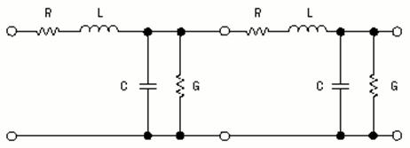
Figure: Electric model for cables as type A
A diagram for the magnitude of the Profibus signal by distance and frequency shows a figure
similar to the example below:
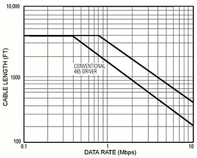
Figure: Magnitude by frequency
Based on the above figure and the cable characteristics, the maximum length for a Profibus DP networks segment is found on the table below:
|
B. Rate (Kbps) |
9.6 |
31.25 |
45.45 |
93.75 |
187.5 |
500 |
1500 |
3000 |
6000 |
12000 |
|
Distancia (metros) |
1200 |
1200 |
1200 |
1000 |
1000 |
400 |
200 |
100 |
100 |
100 |
For a perfect work, it is mandatory the use of terminators [4] and they be positioned at the ends of each network segment. The termination circuit is illustrade below.
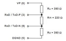
Figura: Termination circuit
However, in order to have a safe way to execute the bus, the characteristic topology must not have complex aspects such as stubs above 1.4Mbps, which will harm the signal integrity. Considering the atenuation problems described above, the repeater is one of the best ways to extend the long network segments.
3- THE RS-485 STANDARD
The RS-485 is a half duplex, bi-directional physical means standard, whose devices are connected under the bus topology. It is the Profibus DP physical means and includes most RS-422 specifications, though being more robust and having bigger input impedance and large differential band.
The input sensitivity is ±200 mV, and to recognize a signal, the receiver needs levels above +200 mV or below -200 mV [5]. The receiver minimum input impedance is around 12 kΩ and the minimum output voltage is ±1.5 V and the maximum ±5 V. These tolerances are fundamental for the repeaters operation, since both segments made up of RS-485 drivers.
The driver impedance is around 54 Ω, which includes typically a 22 AWG twisted pair, combined with 32 stations in paralel with termination in 390 – 220 -390 Ω.
A RS-485 maximum capacity is 32 estations, i.e., 32 loads of 12 kΩ in paralel. Any combination of receivers can be used as long as respecting the maximum limit of 32 loads in paralel, namely, 375 Ω.
For this motive, the use of repeaters is fundamental to meet the maximum quantity of Profibus Field devices, which is126 stations.
4- THE REPEATERS
Repeaters Profibus network are active elements that interact directly on the circuits they are connected to, reconstructing the domain of time or signal amplitude of the degraded or distorted signals along the network segment by the cables of any element connected to it. They must not interpret the protocol, i.e., they must have the shortest possible time deviation in relation to the original telegrams. Below is an illustration of the use of repeaters.
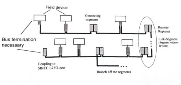
Figure: Topology with Profibus repeaters
A deviation is typically found on the 1-to-2 Tbit order. Although modern digital circuits have delays in the nanoseconds order, these deviations occur basically due to distortions existing in galvanic and optical isolations, and the processing time the repeater needs to handle the signal to reject noises ou information. Once 1Tbit is taken, the repeater will make the signal consecutive analysis to reject inconsistent noises or information. Some modern repeaters use techniques of data collision detection.
Profibus DP telegrams use the NRZ (Non Return to Zero) code, whose characteristic is the absence of signal transcription during the Tbit. Tbit is the time of 1 Bit transmission: TBit=1BaudRate
TBit=1BaudRate
This is the period when the modern repeaters process each bit, filter invalid Bits increasing the rejection to noises and distortions and regenerate the signal.

Figure: 1- Byte Stream serial
Generally, repeaters control the flux of data in the segments.It must be reliable and robust, since the failures in its power supply or connections may harm the protocol correct flux. Some repeaters feature the detection of data collision between the segments. Below is an illustration of 2 repeaters in parallel.
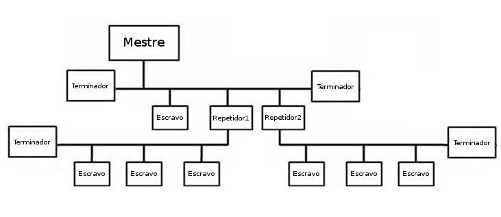
Figure: typical repeater topology
The maximum quantity of repeaters to be employed in cascade is not defined by specification and is limited exclusively by the manufacturer´s technology.
Currently there are repeaters defined to be used by 5, 6 and even 9 units, although other repeater families have a cascade configuration practically without limitation, as those capable to regenerate the Tbits [6]. These repeaters present the best results, as Tbits suffer less distortion with times below 5%. For one Baudrate in 12 Mbps this means a deviation smaller than 4ns.
With the technology used in regeneration repeaters, the most modern models recreate now the Tbits. The transmission is no longer a mere redirectioning of telegrams from one segment to another, but a truly new time base definition with direct signal correction
This result makes possible mapping each telegram transition, increasing the physical layer reliability and robustness, and reducing the rates of communication errors. The network analyses became easier, as the previous distortions in the cascade are now disregarded.
5- FILTERING
Another advantage of using repeaters is that some of them have digital filters ou antiglitch filters, since they feature high capacity information processing . This processing provides bigger communication band gain, which enable their use under the most critical circumstances. Below is the comparative image of the filter processing in a situation with disturbances.
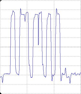
Figure Telegram with coupled noise
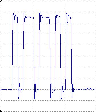
Figure Telegram with filtered noise
According to results above,Profibus telegramas with cyclical data exchange like Data Exchange in the presence of distortions would require a new communication attempt, i.e., a Retry and the digital filter incorporated in the repeater decreases the rate of erros in the physical layer.
6 – COMPARATIVE ANALYSIS
For comparative analysis is used a topology similar to that on Figure 6, by using two repeaters in parallel, as shown on Figure 9.
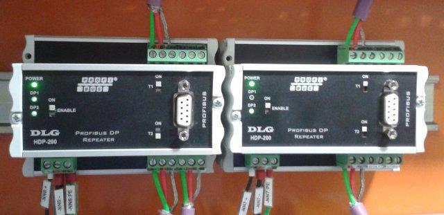
Figure: Profibus DP Repeaters
Below is described the comparison of a segment that begins to show distortions, such as a CCM distant control panel and the corrected segment with the use of a repeater.
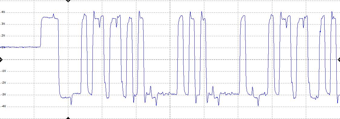
Figure: Differential signal before the repeater
We notice that several harmonic components can be added to RS-485, reaching the limit in the form of communication failures and communications attempts without success, as shown on Figure 7.
With the use of modern Profibus repeaters, regions with high noise density can be segmented with a digital filter ou anti-glitch filter, treating them and ing new regions as valid. For Figure 11 the telegram is the same on Figure 10, however with amplifications and consequent regeneration of Profibus telegramas after using the repeaters.
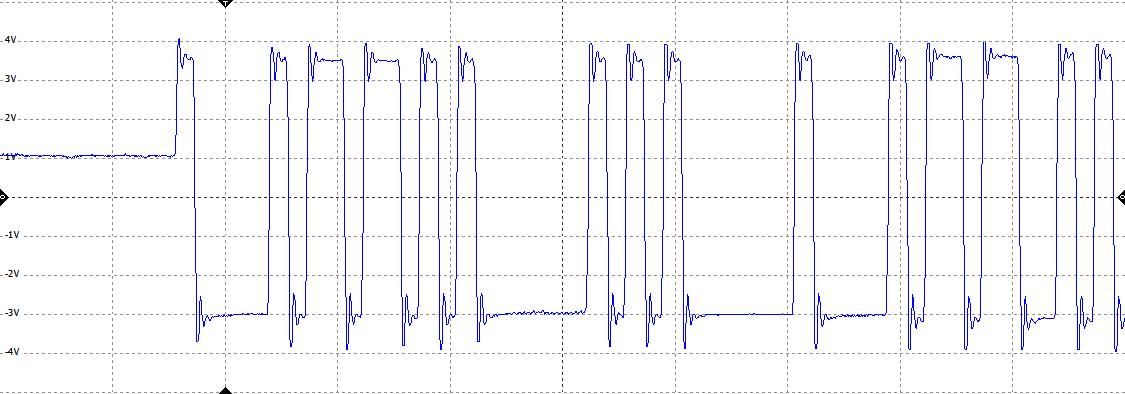
Figura: Diferential signal after the repeater
7- CONCLUSION
The growing use of Profibus networks surely requires techniques more robust and reliable for coltrol loops and plants requiring high degree of intensity. Therefore, repeaters are more and more used to correct several problems covered by this article, namely: quantity of stations exceeding 32 nodes, the nees for using high baudratesf or distances longer than 100m, disacoupling of noises with attenuation of common-mode harmonic components present in the differential signal of communication cables and general-use tool for segmentation of problems.
ACKNOWLEGMENTS
My sincere appreciation to DLG Research & Development Division for its contribution and resources necessary to conduct the production of this paper.
BIBLOGRAPHICAL REFERENCES
[1] PROFIBUS NUTZERORGANISATION, The New Rapid Way to PROFIBUS DP: from DP-V0 to DP-V2, 2003
[2] PI – PROFIBUS & PROFINET International http://www.profibus.com/index.php?id=64#25
[3] Products Meet the PROFIBUS Requirementshttp://www.belden.com/products/browse/industrial/Profibus.cfm
[4] IEC61158-2 – Fieldbus specifications – Part 2: Physical layer specification and service definition, ED5.0, 2010
[5] Guidelines for Proper Wiring of an RS-485 Network http://www.maxim-ic.com/app-notes/index.mvp/id/763
[6] HDP-200 Manual do usuário Repetidor Profibus DP, V1.00, 2012http://www.dlg.com.br
ABOUT THE AUTHOR
Leonardo Antonio Vanzella
DLG Automação Industrial Ltda.
Rua José Batista Soares, 53 – 14176-119 – Sertãozinho – SP.
Telefone: (16) 3513-7400
Fax: (16) 2105-1300
E-mail: leonardo@dlg.com.br
To download this article click here